According to the national regulation on electrical grids, the portion of distributed power generation by PV and wind power should not exceed 10% of the electrical grid. An energy storage system is required if it exceeds this percentage. If there is no energy storage system in PV systems or wind power systems, it will result in adverse effects on the electrical grid. When the scale of the wind power systems or PV power generation systems keep increasing and the percentage of PV power within the systems keep increasing, these effects will become non-negligible. It is known from the analysis of characteristics of PV power generation that the influence of a PV generation system on the electrical grid is mainly due to the instability of PV powers. To ensure the safe, stable, and economical operation of electrical grids, typically it is required to install an energy storage system. As a result, the demands for energy storage systems have increased for the last couple of years.
The stable operation of an energy storage system is closely related to the safety and stability of the electrical grid. Therefore, every major energy storage system manufacturer emphasizes very much on the quality of their products. Among the factors that affect the stability of an energy storage system, the cooling performance is no doubt the most important one. Winshare Thermal has been focusing on the high power cooling techniques and has abundant experiences in the development and manufacturing of cooling solutions for energy storage systems. We are also capable of further optimizing the cooling performance of energy storage systems. Via abundant thermal design data that we have accumulated for years, Winshare Thermal can provide accurate thermal simulation and thermal management testing data.
Schematic of the simulation model for the inverter:

Schematic of the inverter module composition:
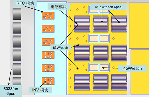
Schematic of the inverter module composition, heat-dissipating component distribution and relevant parameters:
Parameters of INV module:
IGBT:317.2W,no other additional heat consumption;
Thermal conductive interface:0.1MM����,K=4W/m*K;
IGBT Rjc=0.74K/W�,diode Rjc=0.84 K/W���。
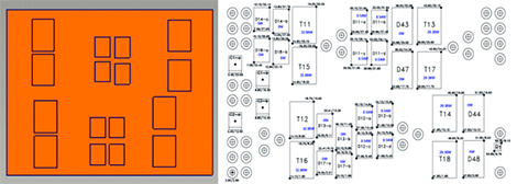
(Figure) Distribution ofRFC heat-dissipating components and IGBT power consumption parameters
Parameters of RFC module:
IGBT:223.8W��,no other additional heat consumption;
Thermal conductive interface:0.1MM,K=4W/m*K;
IGBT Rjc=0.65K/W diode Rjc=0.86��。
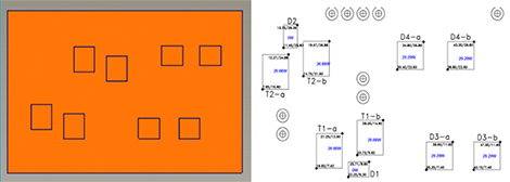
(Figure) Distribution ofRFC heat-dissipating components and IGBT power consumption parameters
Schematic of the fan used in simulation:
A Minebea06038DA-12R-EUD-1 15000RPM fan is used

Schematic of the placement of heat sinks for the inverters of the energy storage system in the simulation (see 3D model)

Schematic of the heat dissipation velocity of the heat sinks for the inverters of the energy storage system along a cross section:
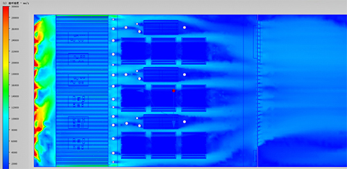
Schematic of the vector dissipation of the heat sinks for the inverters of the energy storage system along a cross section:
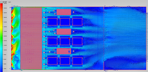
Simulation results and schematic of the airflow vector dissipation:

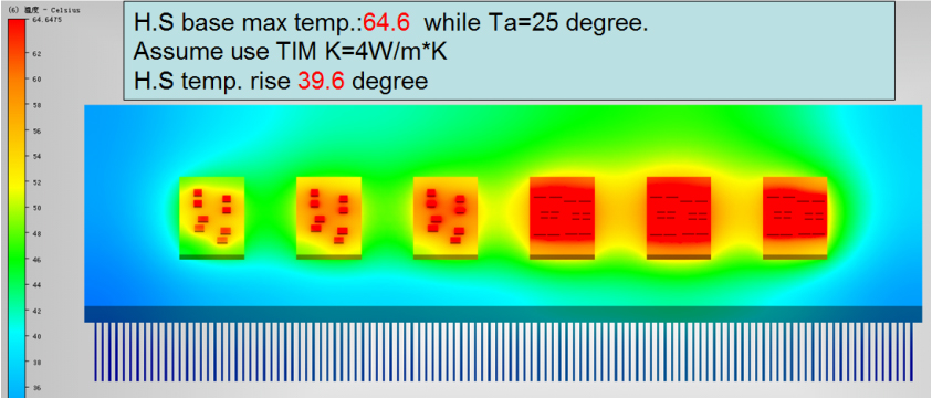
Simulation results and schematic of temperature dissipation of the heat sinks for inverters:
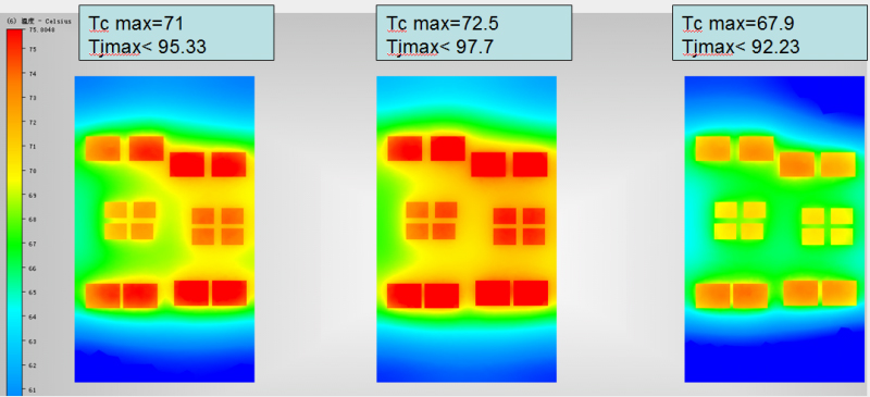
Simulation results and schematic of temperature dissipation of the heat sinks for INV module:
Simulation results and schematic of temperature dissipation of the heat sinks for RFC module:
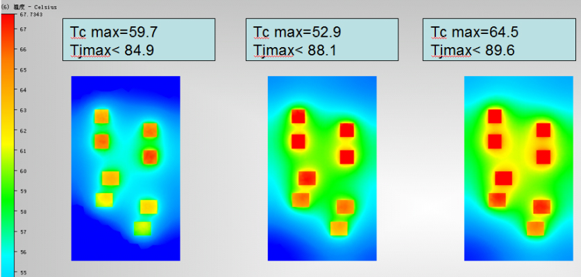
Summary of the simulation results on the heat sinks for inverters of energy storage systems:


