Power batteries serve as the power source for machines and especially serve as the storage batteries new energy vehicles such as electric cars and electric trains. New energy cars means those which use non-conventionalautomotive fuels and advanced technologies that integrate the power control and driving aspects of vehicles so as to form a vehicle that has new technology and new structures based on advanced technical theorem. People see a bright prospect for new energy cars due to the characteristics of being energy efficient and environmental-friendly and there is also a great support from the government on relevant strategies. To implement and fulfill the deployment and demands by the State Council on the cultivation of strategic emerging industries and the strengthen of energy-efficient and carbon-reduction tasks, the financial department of the central government approved special funds for supporting and developing subsidy pilot areas for people to buy new energy cars.
A new energy car is composed of the battery driving system, electrical motor system, electrical control system, and assembly. Among these portions, the electrical motor, electrical control, and assembly are basically the same as those of a conventional car. The main difference lies in the power source. Power battery packs are the critical power source to a new energy car. A wide variety of new energy car manufacturers increase the scale of their development in the power battery packs with an attempt to overcome the bottlenecks of higher cost, lower battery life, lower battery charging speed, etc. Moreover, they have been working with thermal companies such as Winshare Thermal on resolving the power battery pack cooling problems so as to enhance the performance of power battery packs.
Winshare Thermal is dedicated to become the leader in the thermal management of the new energy filed. We have abundant experiences in the development of power battery pack cooling techniques. Winshare Thermal's engineers carry out thorough investigation with car manufacturers and have helped new energy car manufacturers resolve their cooling problems and we are widely acclaimed in this industry.
Schematic of the simulation models of power battery packs and cold plates:
Five cold plates out of the entire system are selected for the demonstration of this cooling solution and the total power is 1400W.
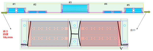
(1)Cold plate A: 476* 134.4; source size:179.2*134.4;
(2)The area in light red is dissipating heat, 136.5W/each,total 273W;
(3)The figure indicates the distribution of water flows, the bottom cove is 3.0mm thick, the top cover is 4.0mm thick,
and the fins in the middles is 3.0mm thick. Fin thickness 1.0mm, gap 3.0mm, fin length 164mm with a totalof 22fins;
(4)The middle cylinder (D10) is the location for structural enhancement (sealed up after fixed by screws).

(1)Cold plate B: 476* 57.4; source size:177*44.3;
(2)The area in light red is dissipating heat, 44.5W/each,total 89W;
(3)The figure indicates the distribution of water flows, the bottom cove is 3.0mm thick, the top cover is 4.0mm thick,
and the fins in the middle is 3.0mm thick. Fin thickness 1.0mm, gap 3.0mm, fin length 165mm with a totalof 9fins.
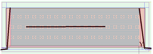
(1)Cold plate C:670*240; source size:663*180;
(2)The area in light red is dissipating heat, total 676W;
(3)The figure indicates the distribution of water flows, the bottom cove is 3.0mm thick, the top cover is 4.0mm thick,
and the fins in the middle is 3.0mm thick. Fin thickness 1.0mm, gap 4.0mm, fin length 610mm with a total of 7*4=28fins.
Schematic of thermalsimulation results of the cold plate for power battery pack #1:
(1) Schematic of the cross-sectional velocity distribution profile within the cold plate:

(2)Schematic of the cross-sectional pressure distribution profile within the cold plate:

(3)Schematic of the cross-sectional temperature distribution profile within the cold plate:
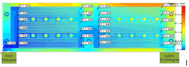
(4) Schematic of the simulation results of cold plate temperature profile:
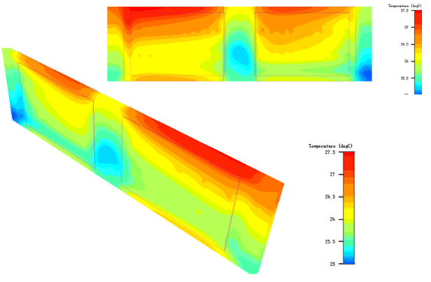
Schematic of thermalsimulation results of the cold plate for power battery pack #2:
(1) Schematic of the cross-sectional velocity distribution profile within the cold plate:

(2)Schematic of the cross-sectional pressure distribution profile within the cold plate:

(3)Schematic of the cross-sectional temperature distribution profile within the cold plate:

(4) Schematic of the simulation results of cold plate temperature profile:
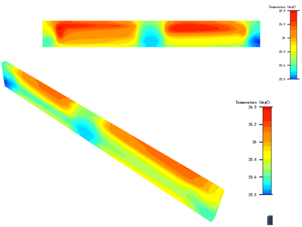
Schematic of thermalsimulation results of the cold plate for power battery pack #3:
(1) Schematic of the cross-sectional velocity distribution profile within the cold plate:

(2)Schematic of the cross-sectional pressure distribution profile within the cold plate:

(3)Schematic of the cross-sectional temperature distribution profile within the cold plate:
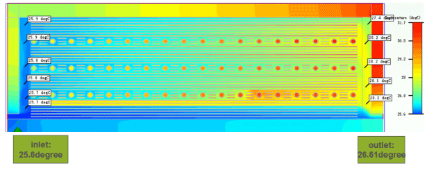
(4) Schematic of the simulation results of cold plate temperature profile:
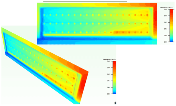
Schematic of thermalsimulation results of the cold plate for power battery pack #4 (Temperature distribution profile):
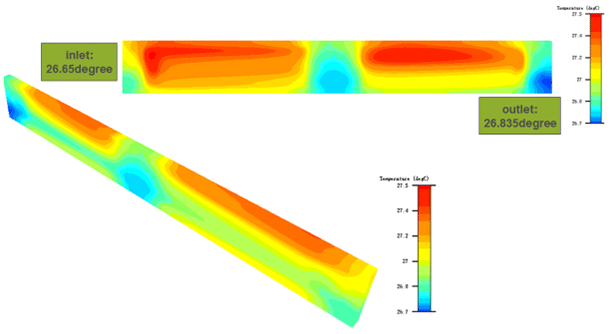
Schematic of thermalsimulation results of the cold plate for power battery pack #4 (Temperature distribution profile):
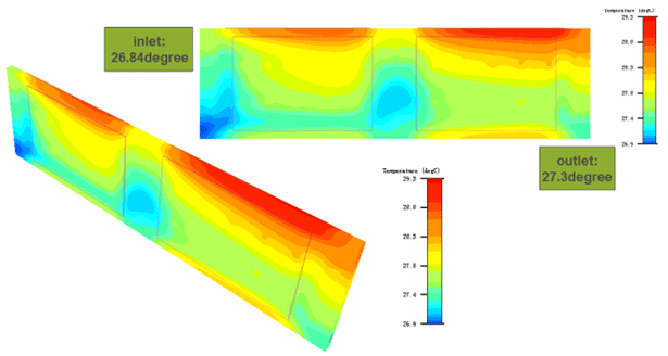
Summary of the simulation data of the cold plate cooling solution for power battery packs:
(1) Coolant:50% ethylene glycol, 50%水, flow rate 10L/min, 25?C;
(2)Outlet water temperature is 27.3?C, temperature difference between inlet and outlet is 2.3?C;
(3) Highest temperature on the heat sink is 29.3?C;
(4)#1 pressure difference 19200Pa, #2 pressure difference 19700Pa, #3 pressure difference 4300Pa;
(5) The overall pressure difference across the model is 19200*2+19700*2+4300=82100Pa.


